
Indoor Wireless Path Loss
Four factors must be considered for transmission range
- By Mike Derby
- Apr 01, 2012
When designing any system, engineers and system architects usually want to know how well the various components of the system will perform. In a microprocessor, logic or other digital system these questions usually are answered in terms of clock speeds, instructions per second or data throughput. With wireless communication, the most common performance questions involve range.
Unlike digital systems, trying to quantify the range performance of radio frequency (RF) communication systems can be difficult due to the large role the environment has on radio frequency signals. Buildings, trees, obstructions and lack of antenna height can all contribute to a decrease in signal strength at the receiving end. In order to estimate the communication distance (transmission range) for a system, four factors must be considered:
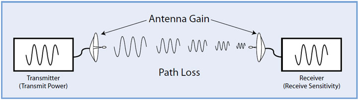
Transmit power. The power that is broadcast by the transmitter. This is usually measured in watts or milliwatts.
Receive sensitivity. A measure of the minimum signal strength that a receiver can discern.
Antenna gain. The amount of signal gain provided by the antennas.
Path loss. The signal decrease that occurs as the radio waves travel through the air or through obstacles.
Path loss or attenuation of RF signals occurs naturally with distance. Obstacles between the transmitter and receiver also attenuate signals. The amount of attenuation varies with the frequency of the RF signal and the obstructing materials’ type and density.
Generally speaking, the lower the frequency of transmission, the better the signal will travel through the air and through objects. If two radio systems had identical transmit power and receive sensitivity, but one system was at 900 MHz and the other at 2.4 GHz, then the 900 MHz radio would perform better because it has less path loss than a 2.4 GHz system. These parameters can be used to estimate the distance a system can communicate.
Knowing how strong the communication link is or just how close a system is to failure can be important in some situations. Link margin is a parameter that is used to measure how close the link is to failing. Link margin is the difference between the system gains and the system losses. Successful communication takes place when the link margin is greater than zero.
Link Margin = Transmit Power – Receiver Sensitivity + Antenna Gain – Path Loss
Comparing an RF communications system to human voice communication can help illustrate these principles. Transmit power represents the volume of the person speaking. Receive sensitivity represents the minimum volume required by the listener to discern the message. Antenna gain is equivalent to the use of a megaphone, and path loss is the attenuation that occurs as the voice travels over a distance or through obstacles.
The transmit power on the indoor AvaLAN AW900iTR is 125mW (21 dBm). The receive sensitivity on the same unit is -97 dBm. If you were to use these radios in a system with 2.5 dBi gain antennas, there could be 123 dB of signal attenuation between the transmitter and receiver and still have communication occur.
21 dBm – (-97 dBm) + 2.5 dBi + 2.5 dBi = 123 dB
In line-of-site conditions, every 6 dB of link margin will double the transmission range. A radio with a link margin of 111 dB has 12 dB less link margin than the AvaLAN radio, and thus it can achieve only a quarter of the range. In line-of-site conditions, the path loss can be determined by using a mathematical formula—the Friis transmission equation. The path loss for 900 MHz and 2.4 GHz in free space is given for several distances in Table 1.
Figuring out the range for nonline- of-site and indoor communication systems is a lot more difficult and can involve a lot of obstructions and variables. The different obstacles and materials that are found in typical indoor environments make it difficult to determine the actual path loss in a given situation. In order to know how systems will perform in a given indoor environment, on-site testing must be performed. If there are known obstructions of a particular material, then estimation of signal losses through the obstruction may aid in determining link margin and antenna placement.
For indoor communication, the construction materials that make up the obstructions are the largest attenuators. Table 2 lists common construction materials and their approximate attenuation at 900 MHz (thicknesses of materials are given in parenthesis).
Solid metal structures are not listed in the tables and graphs in this article because radio waves do not propagate through metal. In practice, metallic masses such as towers, panels, fences or vehicles that are present in the vicinity of radio-transmitting equipment and the radio receiver act as reflectors and scatterers of electromagnetic radiation. The interference of the direct wave and the reflected waves can produce local maxima—constructive interference— or local minima—destructive interference— at the radio receiver.
Example: Suppose there exists a situation where it is desired to communicate 100 meters through four standard sheetrock walls and one concrete wall. Table 1 indicates that the free-space loss for 100 meters at 900 MHz is approximately 93 dB. In this particular indoor situation, it is necessary also to take into account the effect the walls will have on communication. The office walls consist of two pieces of drywall (-0.8 dB each) and lumber (-2.8 dB) for a total attenuation of about 4.4 dB per wall. The concrete wall is 102 mm thick and attenuates the signal by 12 dB. Use this equation:
Power (TX) - Sensitivity (RX) >= Signal Attenuation 148 dB >= 93 dB + (4 walls * 4.4 dB) + (12 dB) 148 dB >= 122.6 dB
The link margin of 148 dB is greater than the path loss of 122.6 dB, allowing communication to occur. It should be kept in mind that this is only a theoretical estimation. An on-site test should be performed in order to verify conditions and assumptions.
When trying to determine just how far any particular radio will transmit indoors, the main difficulty lies in figuring out just what path the radio signal will take and how many walls and obstacles the signal must transmit through. While taking into account the different building materials and their thicknesses can be helpful for estimation purposes, testing in the actual environment is the only sure way to determine whether or not communication will be successful.
The radio transmit power, receive sensitivity and frequency need to be considered in any wireless communication system. Antenna or radio placement can help in avoiding some obstacles, but in most situations the system designer does not have control over what building materials must be transmitted through. That leaves transmit power, receive sensitivity and antenna gain as the only parameters that are left to the designer’s choosing.
If communication in a particular environment is not robust, choosing a radio set with better link margin can help improve data reliability. The expectation should be that some data will be lost. Protocols can be developed that allow for graceful recovery from data corruption and reliable delivery of the information. Estimating materials and doing site testing in the actual environments can aid in establishing performance expectations during the design phase of the system.
This article originally appeared in the April 2012 issue of Security Today.
About the Author
Mike Derby is the chief technology officer and founder of Ava-LAN Wireless.